Matrix
A matrix in audio refers to a flexible routing system that allows multiple inputs to be sent to multiple outputs. A mixer controls the blending, balance, and routing of these signals, determining how they combine before reaching their destination. A matrix mixer combines these functions, enabling signals to flow through complex audio paths. Matrix mixers vary in design, with differences in signal-path architecture, attenuation options, routing capacity, and switching mechanisms. Due to this variation, and the potential complexity of their interfaces, matrix mixers are often viewed as highly technical tools, which can make integration into music-centered workflows challenging.
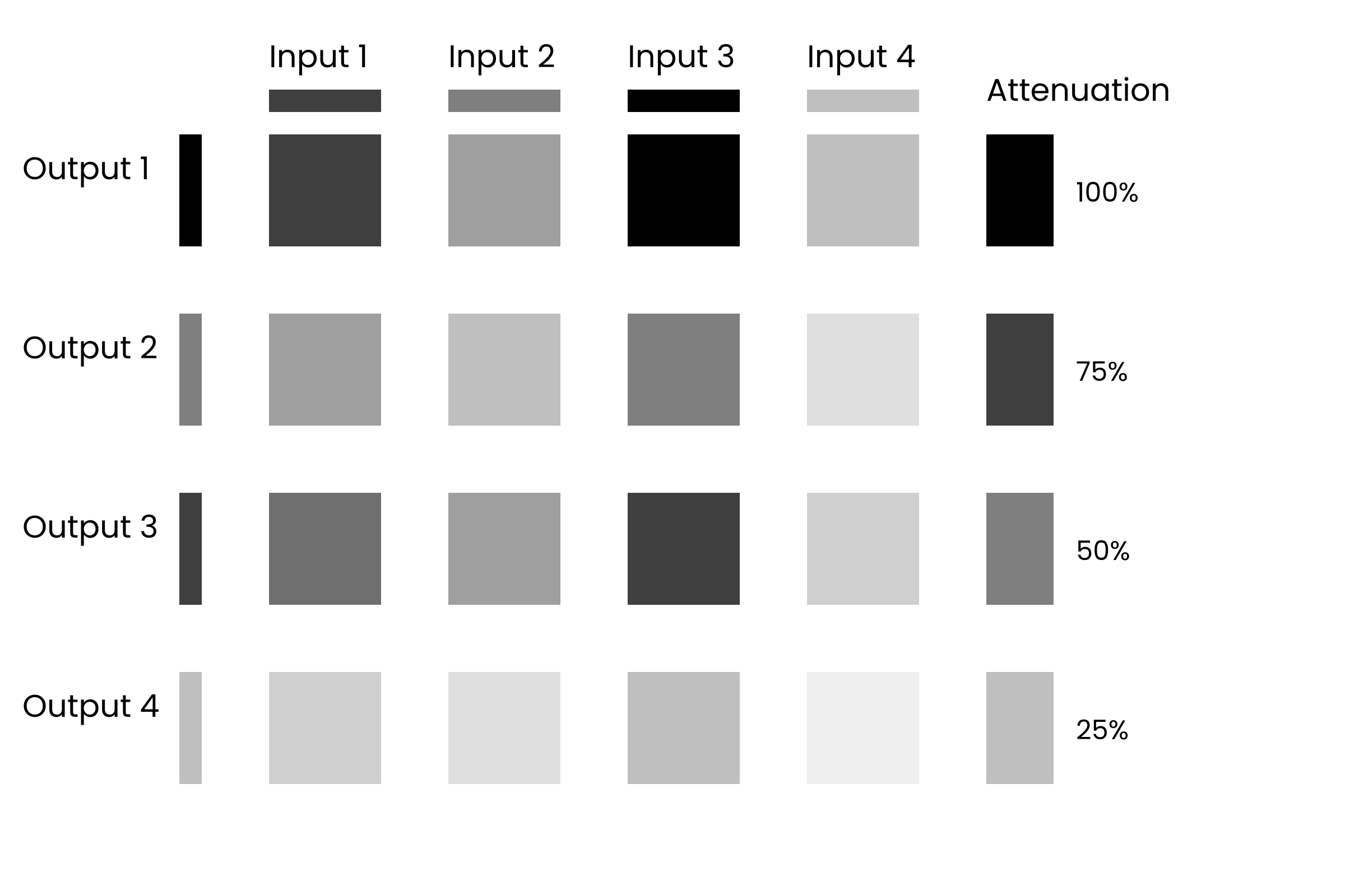
Reliq approaches the matrix mixer as a musical instrument, designed to explore new musical ideas through flexible audio signal routing. Built with 16 inputs and 16 outputs in a fully analog signal path, the matrix features attenuation at both inputs and outputs. Any input can be routed to one or more outputs, allowing for a wide range of routing configurations. These configurations can be stored and recalled in real-time, facilitating quick changes without interruption. An integrated anti-pop and anti-click filter ensures smooth transitions without introducing noise or artifacts during routing changes.
The matrix supports real-time sequencing of Routings, enabling dynamic adjustments to signal flow in sync with musical timing. High-resolution attenuation provides precise control over input and output levels.
A grouping function allows inputs and outputs to be organized by criteria such as type or size, making complex routing setups easier to manage. This organizational approach helps keep the interface intuitive and reduces the complexity often associated with larger routing matrices.
The Reliq matrix aspires to facilitate rapid exploration of different routing configurations, making them an integral part of the music-making process.
Interface Overview
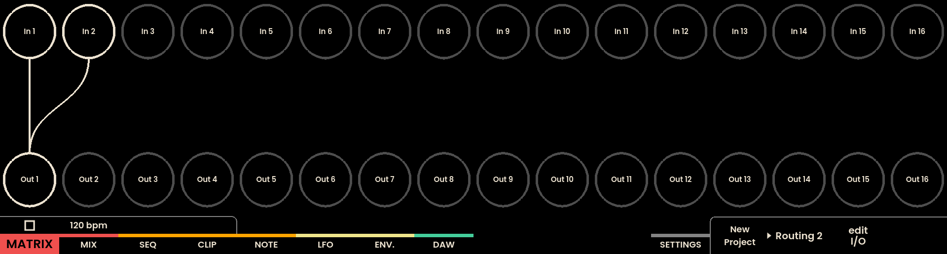
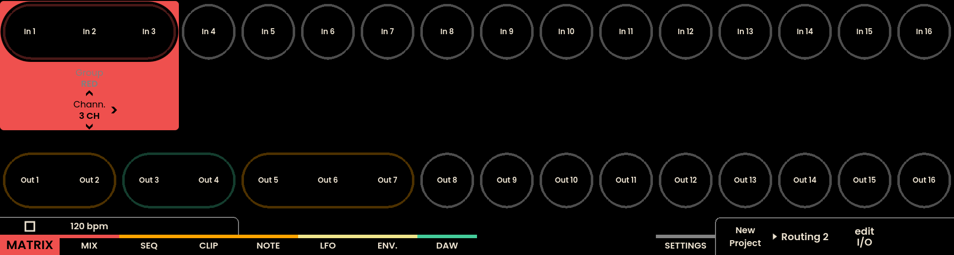
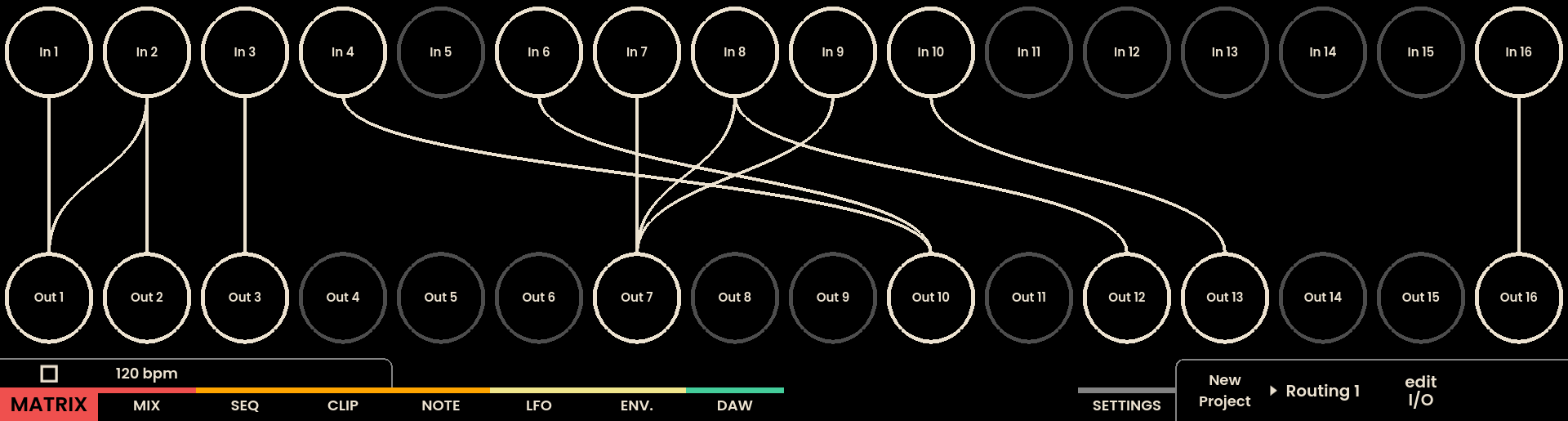
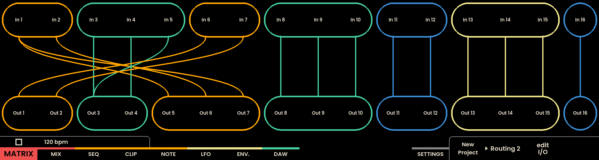
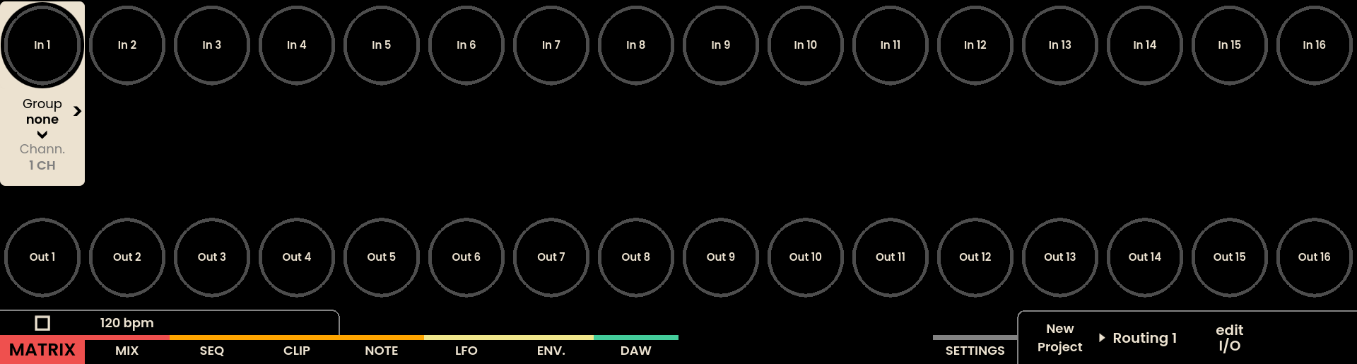
The Matrix page on Reliq’s display is divided into two horizontal sections. The top section features sixteen circular nodes, each representing one of the 16 inputs on the Breakout Module. The name of the input is displayed at the center of each node. In the bottom section, 16 circular nodes represent the outputs on the Breakout Module. When a connection is formed, a line visually links the corresponding input node to its output.
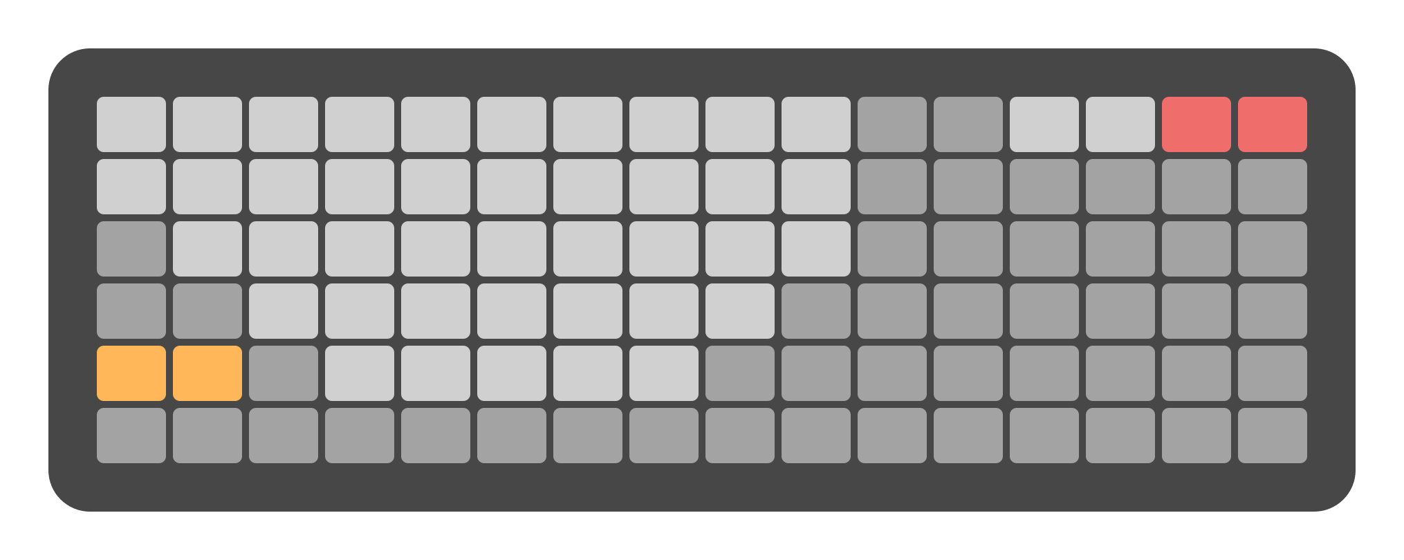
On the Grid Pads, inputs are arranged along the horizontal axis (columns), while outputs are arranged along the vertical axis (rows).
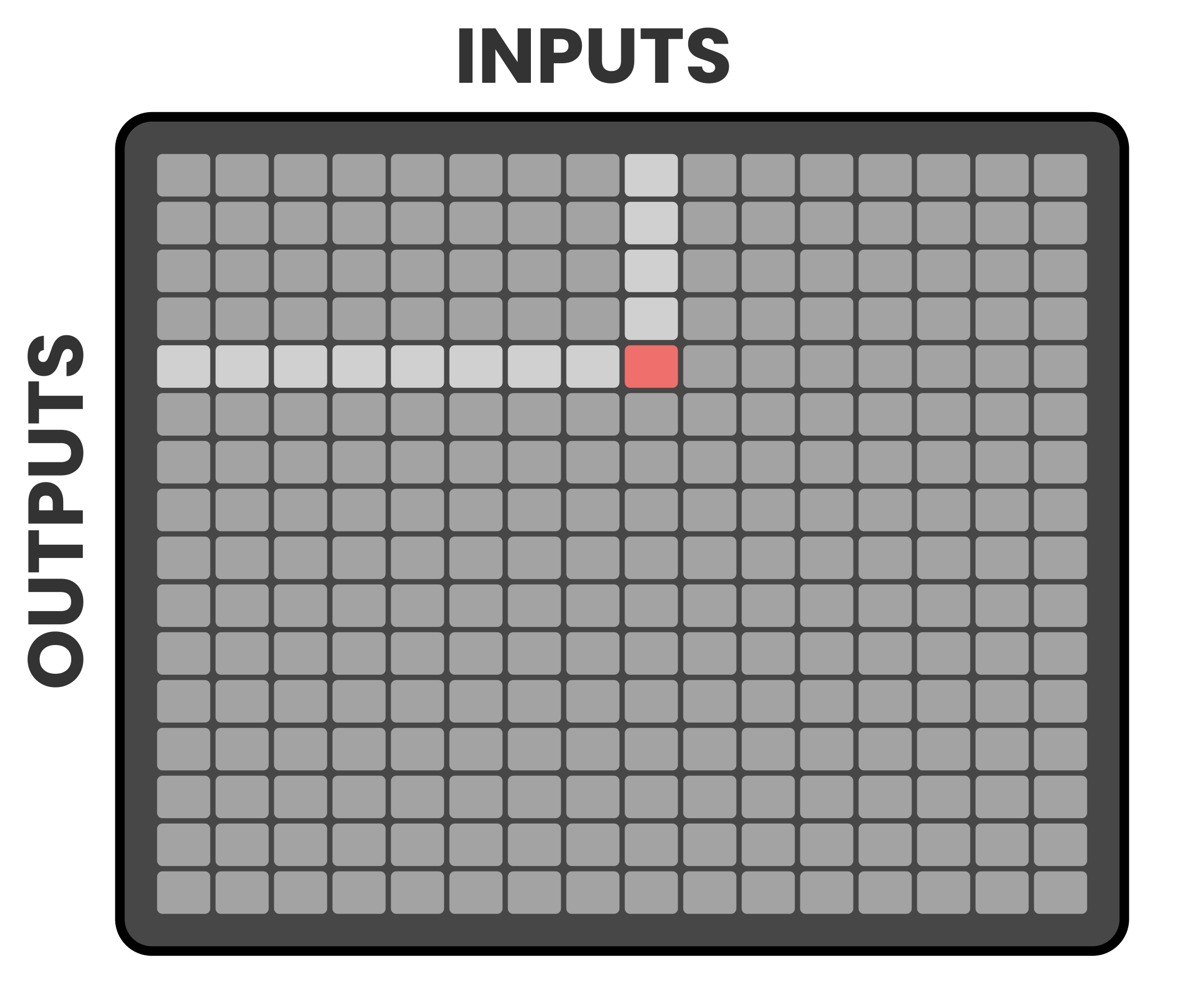
The intersections between rows and columns indicate nodes connections.
When Parameter Lock is activated on a connection, a line appears on the Grid Pads, showing the input/output path.
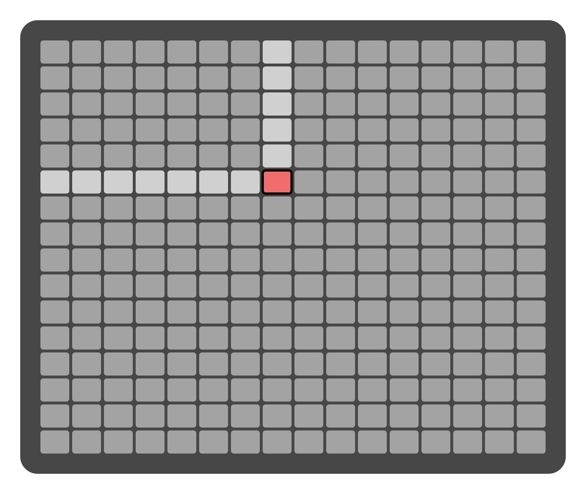
If any inputs or outputs belong to a group, they will be color-coded on the display according to the group they are assigned to, providing a visual distinction for organized routing.
The 16th row of the grid can toggle between normal connection view and routing view by pressing Track Button . In routing view, the pads in this row display both active and stored routings. The currently active routing is highlighted on the bottom-right corner of the display.

Input and output attenuation levels can be adjusted via the Mix Page (see the chapter Mixer for further details).
Making Connections
The interface allows for connections to be made through the Grid Pads. The top portion of the screen displays sixteen input nodes, while the bottom portion displays sixteen output nodes.
Connections can be made between any input and output in two different ways:
Using the LED Grid Pads
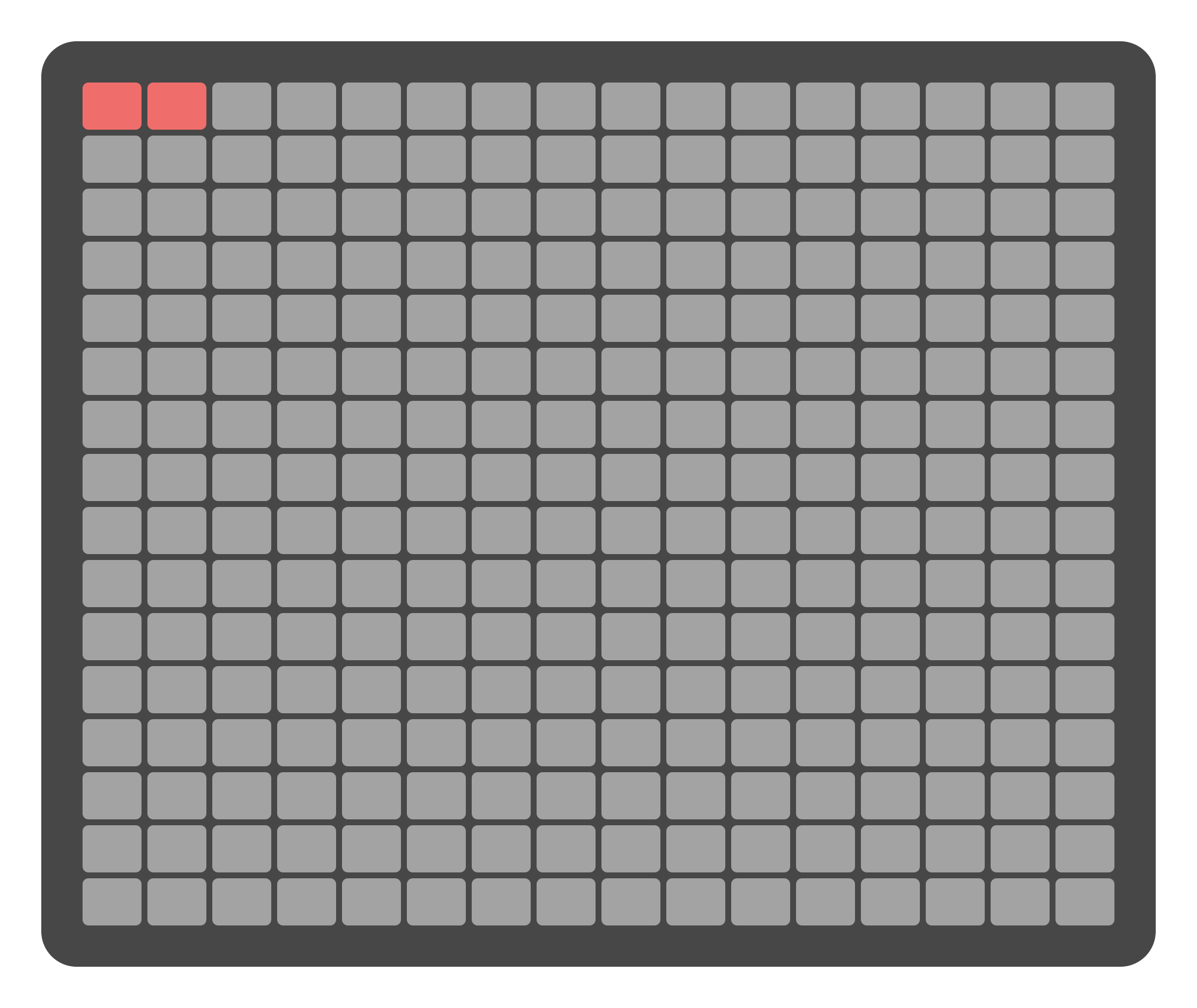
The Grid Pads, offer a visual and tactile interface for making connections. Each column corresponds to an input, and each row corresponds to an output.
Pressing a Grid Pad where an input column intersects an output row will form a connection between them. Holding down any Grid Pad Parameter Lock on the grid will illuminate a line, indicating which inputs are connected to which outputs.
Using the Encoder
Connections can also be made directly via the screen by using the encoders located above each input node. Clicking and holding an encoder will reveal the output labels on the screen. A corresponding output can then be selected by pressing the appropriate Page Button , establishing a connection between the input below the encoder and the outpout above the Page Button .
Saving and Loading Routings
Routings represent saved connection states between the inputs and outputs of the Matrix and the corresponding Mix Page levels. The routing view allows routings to be viewed, saved, and loaded via the Grid pads.
Accessing Routings
The routing view can be accessed by pressing Track Button . Track Button acts as a toggle between routing and connection views. In the Routings view, the sixteen Pads on the bottom row of the LED grid correspond to saved routings.

Saving a Routing
Routings are automatically saved as connections are made.
Loading a Routing
A routing can be loaded by pressing any Grid Pad in the bottom row of the Grid Pads. Lit pads indicate filled routing slots, while unlit pads represent empty Routings.

There are four banks of routings, navigable via the . Routings can also be sequenced using the Matrix Sequencer (refer to the Sequencer chapter for details). Another method for navigating between routings is provided via the Arrow Buttons on the top right of the interface. Pressing the Arrow buttons will trigger the next or previous routing.
Deleting a Routing
To delete a Routing, press and hold the UNDO button and press and hold the Grid Pad of the Routing you want to delete.
Groups
The Matrix provides the ability to group inputs and outputs, allowing for easier connection management when working with multiple nodes. Groups streamline the connection process by enabling the control of multiple inputs and outputs simultaneously.
Creating a Group
Groups are formed via the node selector on the screen and the Joystick Encoder on the upper right part of Reliq . Clicking the Joystick Encoder down will activate the node selector, allowing navigation between input and output nodes using the joystick’s directional movements. By , , and you can navigate on the Group Menu selecting the node, type and size parameters. Rotate the Joystick encoder when the value of each parameter can be adjusted.
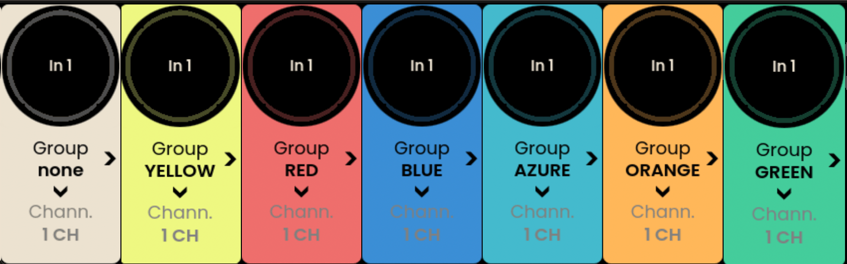
Group Types
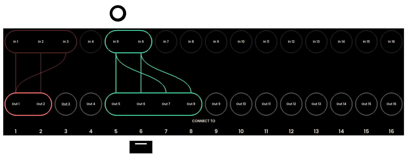
Each group is assigned a color, and only groups of the same color can be connected together. For example, an orange input group can only connect to an orange output group. The number of channels in a group can vary from one channel to the maximum of 16 available channels.
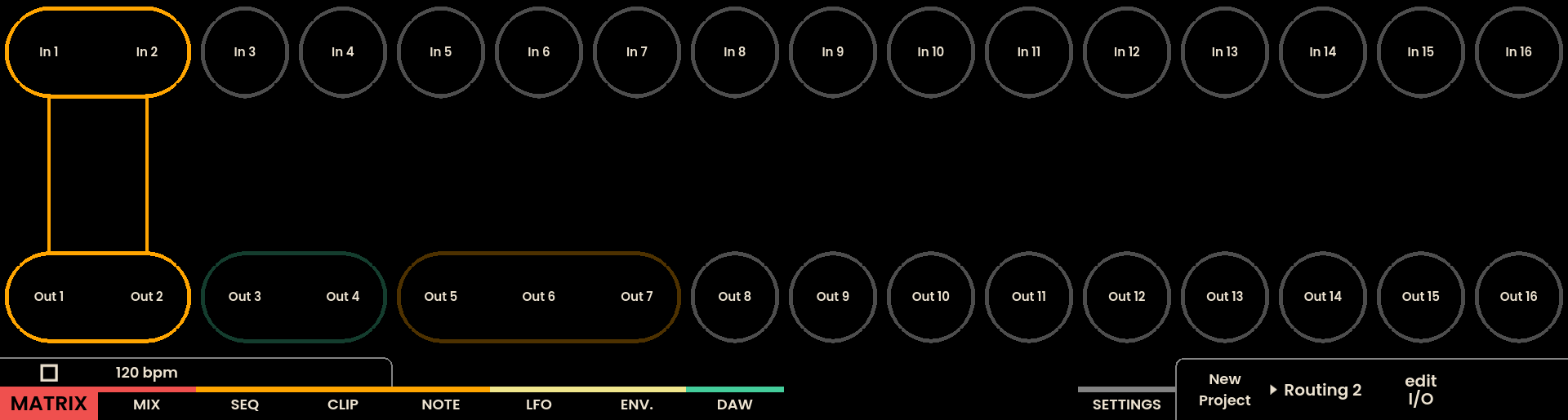
Connecting Groups
Once a group has been created, pressing a single connection point on the grid will connect the entire group of inputs to the corresponding group of outputs. If there is a mismatch between the number of inputs and outputs, Reliq cycles through the connections, forming a repeating sequence. Connections can only be made between input and output groups of the same kind or colour. The WHITE group is a special group that can connect to any other group.

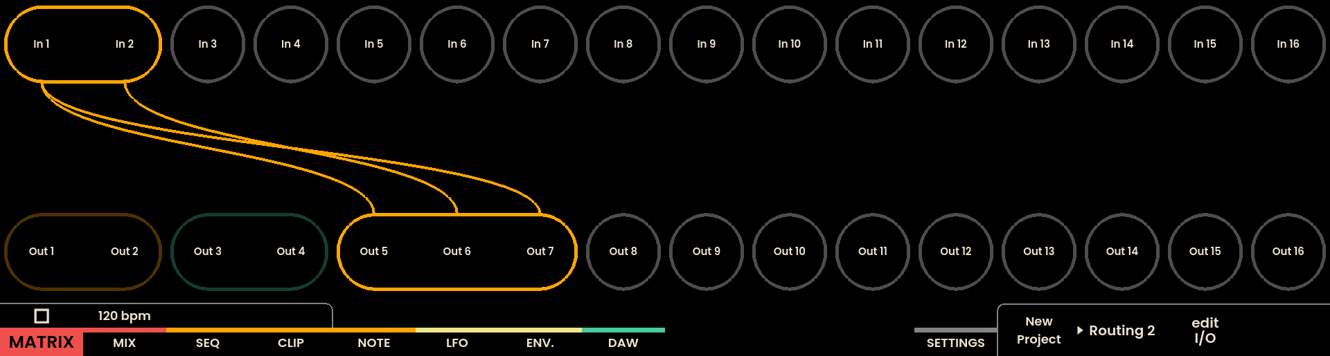
Adjusting Groups
Groups can be adjusted via the encoder located above the selected group on the screen. Rotating the encoder shifts the group connections to the next or previous group of the same color, allowing quick adjustments to be made without recreating group settings.
Connect to the next group with
Naming Inputs, Outputs and Routings
Inputs, Outputs and Routings can be named to provide a way to categorize and intentify specific nodes and connections.
Naming Inputs and Outputs
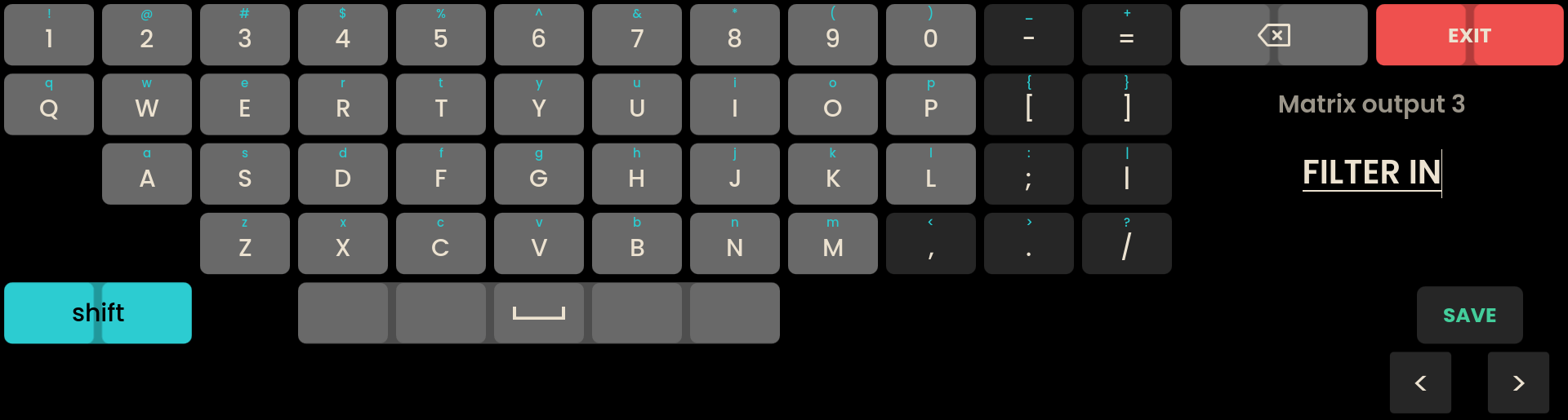
To navigate between inputs and outputs, use the Node Selector. Once the desired node is selected, open the Reliq Keyboard by pressing the Page Button , located below the node name at the bottom-right corner of the screen.
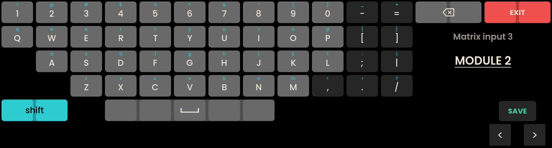
When the Reliq Keyboard is open, rotate the Joystick Encoder to navigate between different inputs and outputs.
The first five rows of the Grid Pads display the available characters, matching the layout of the keyboard on the screen. These pads provide a tactile interface for selecting characters.
- The following buttons are used for additional keyboard functions:
Button: Toggles between lowercase, uppercase, and special characters.
Buttons: Move the cursor left or right within the name field.
Button: Saves the name and closes the keyboard.
Naming Routings
To name a routing, first select the Routing View by pressing the Track Button . Then, press the Page Button located below the routing name at the bottom-right corner of the screen to open the Reliq Keyboard.
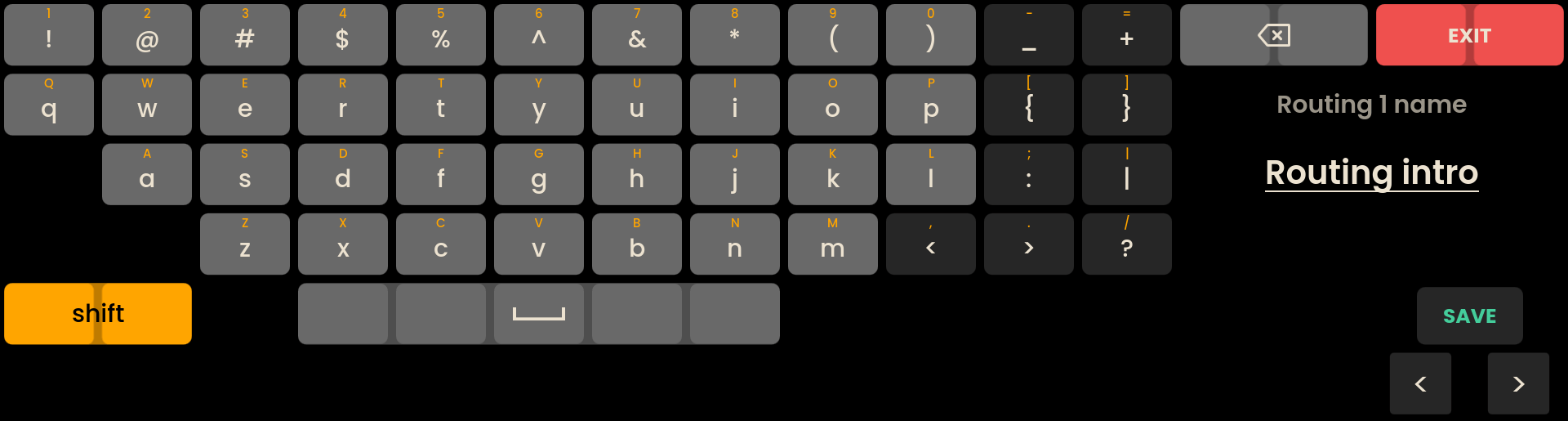
The same workflow and keyboard interface apply to naming routings. Once the desired name is entered, press to save the routing name and close the keyboard.
Technical Specifications
The Reliq Matrix operates entirely in the analog domain within a range of -10V to +10V. The system provides approximately 19.22 dBu of headroom.
Specification | Details |
|---|---|
Range | -10 to +10 V |
Headroom | ~19.22 dBu |
Input Impedance | 100kΩ |
Output Impedance | 51Ω |