
Mixer
The Mix Page in Reliq is closely integrated with the Matrix Page, providing a dedicated interface for controlling the attenuation of each input and output. With 32 high-resolution analog amplitude controls—16 for inputs and 16 for outputs—the Mix Page enables precise control over signal levels.
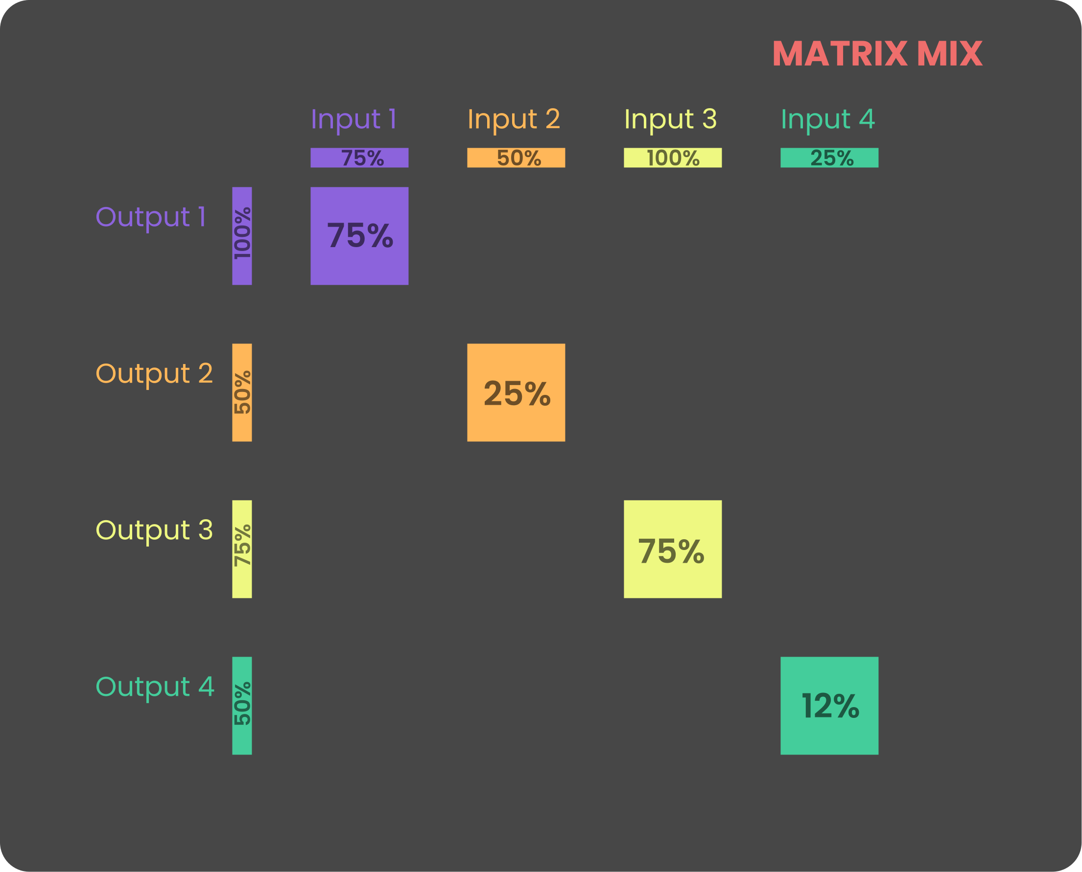
Attenuation operates on two levels: input attenuation and output attenuation. Adjusting the output attenuation controls the summed signal level at each output, while modifying the input attenuation affects the amplitude of that input across all connected outputs. These adjustments are visually represented in the graph below.
The Reliq mixer operates fully in the analog domain and is factory-calibrated to provide unity gain when both input and output attenuations are set to 100%. However, due to the analog nature of the system, factors such as temperature and environmental conditions may cause slight variations in gain.
The Mix Page plays a vital role in shaping the mix within each routing configuration. Every mix setting is saved as part of the active routing and can be dynamically sequenced using the Matrix Sequencer (refer to the Sequencer chapter for details), allowing for real-time control and smooth transitions between different mix configurations.
Interface Overview
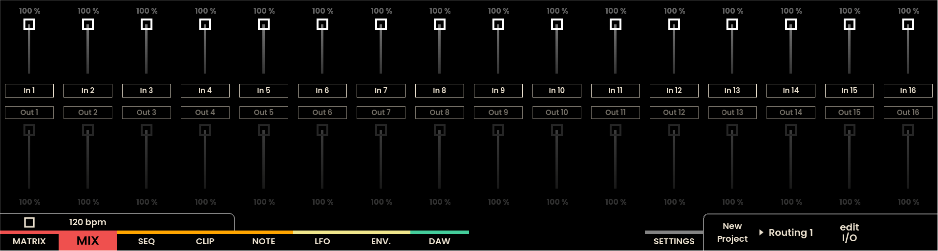
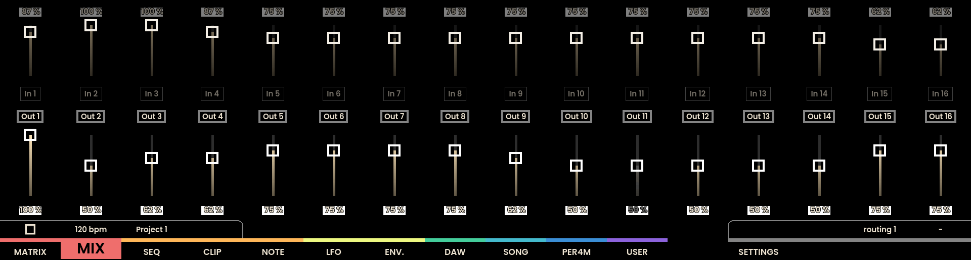
The Mix Page interface on Reliq’s display mirrors the layout of the Matrix Page, with 16 input nodes at the top and 16 output nodes at the bottom. Each node has a ring that indicates the current attenuation, and the level is displayed as a percentage. Each node is color-coded to correspond to the group to which the input or output belongs.
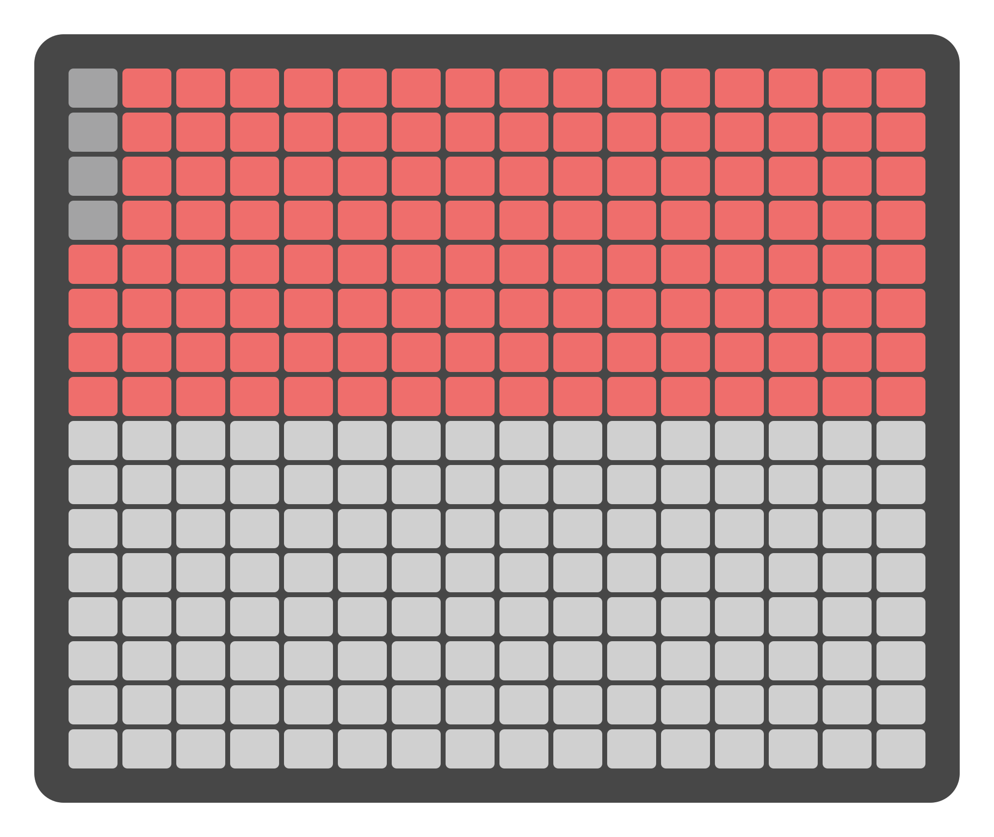
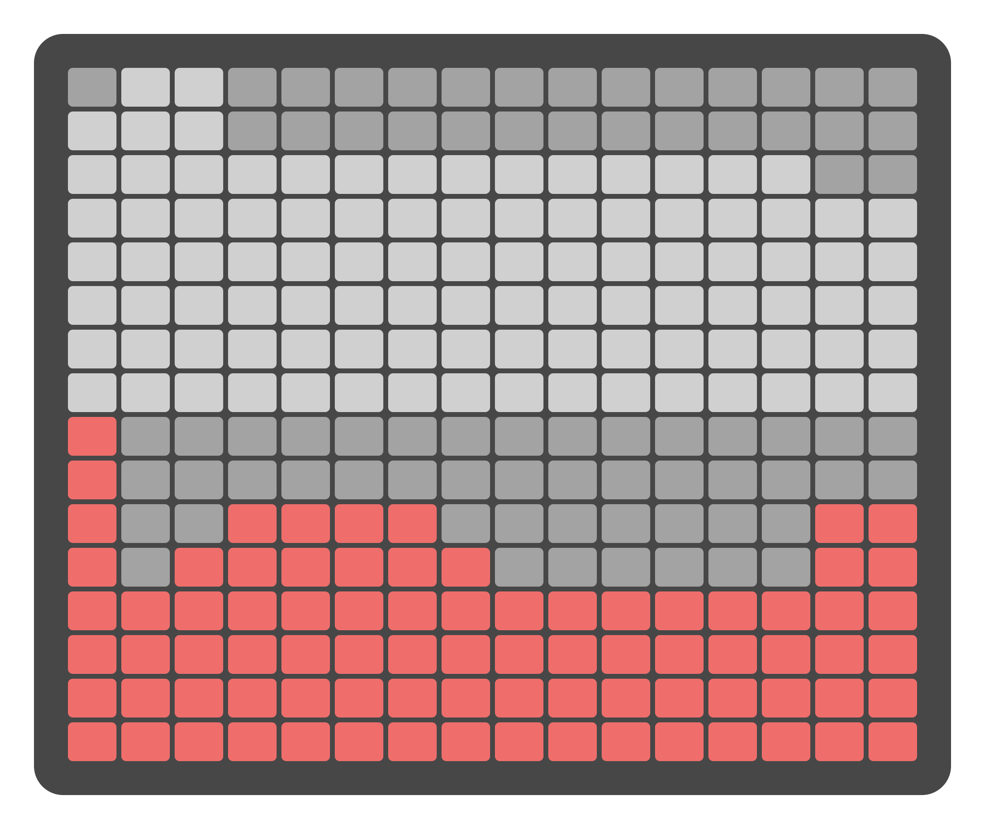
The Grid Pads on the Mix Page offer similar visual feedback as the display. The top half of the grid represents the input levels, while the bottom half represents the output levels. Each column of the grid acts as a virtual fader, visually reflecting the current attenuation level for each input and output.
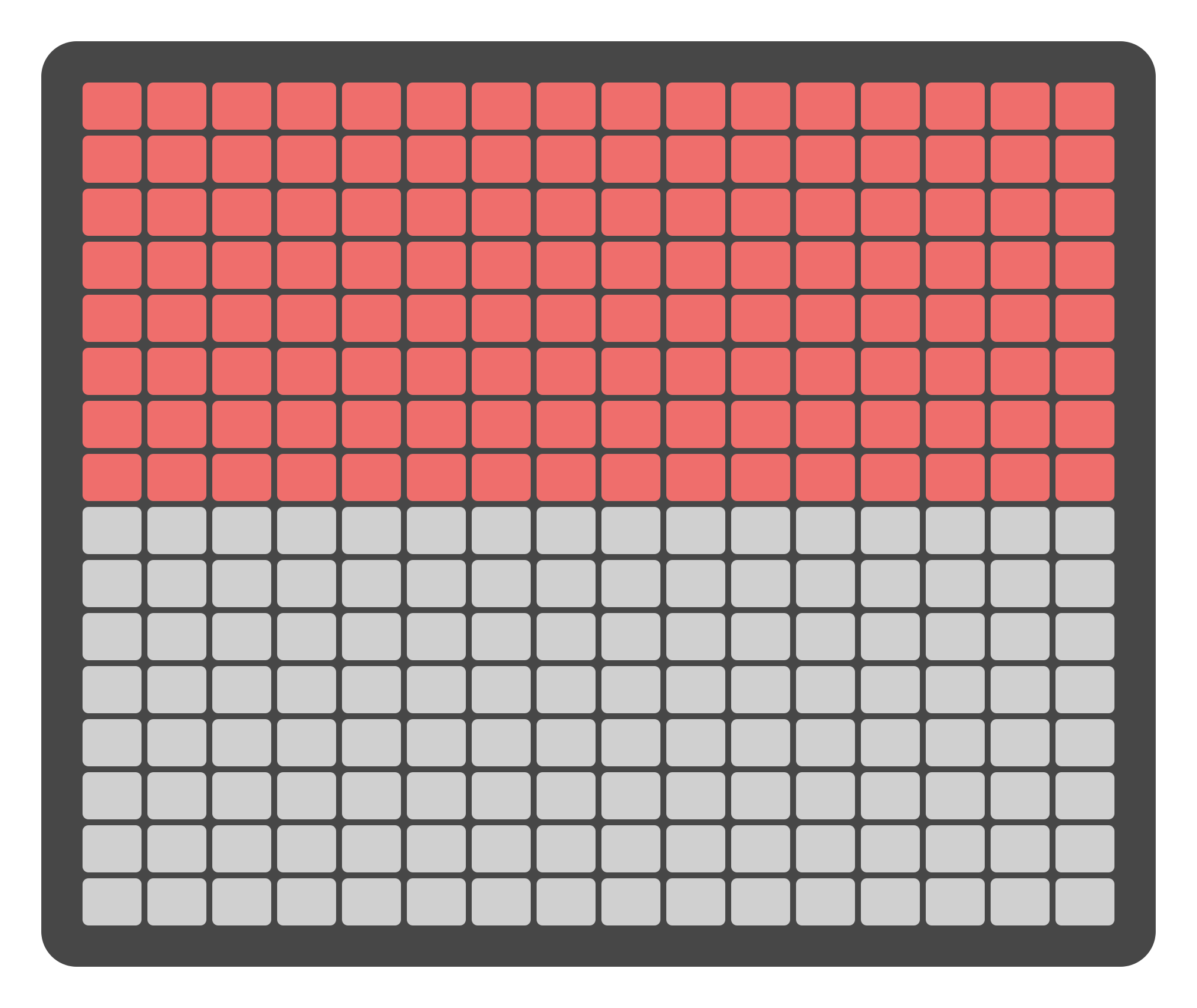
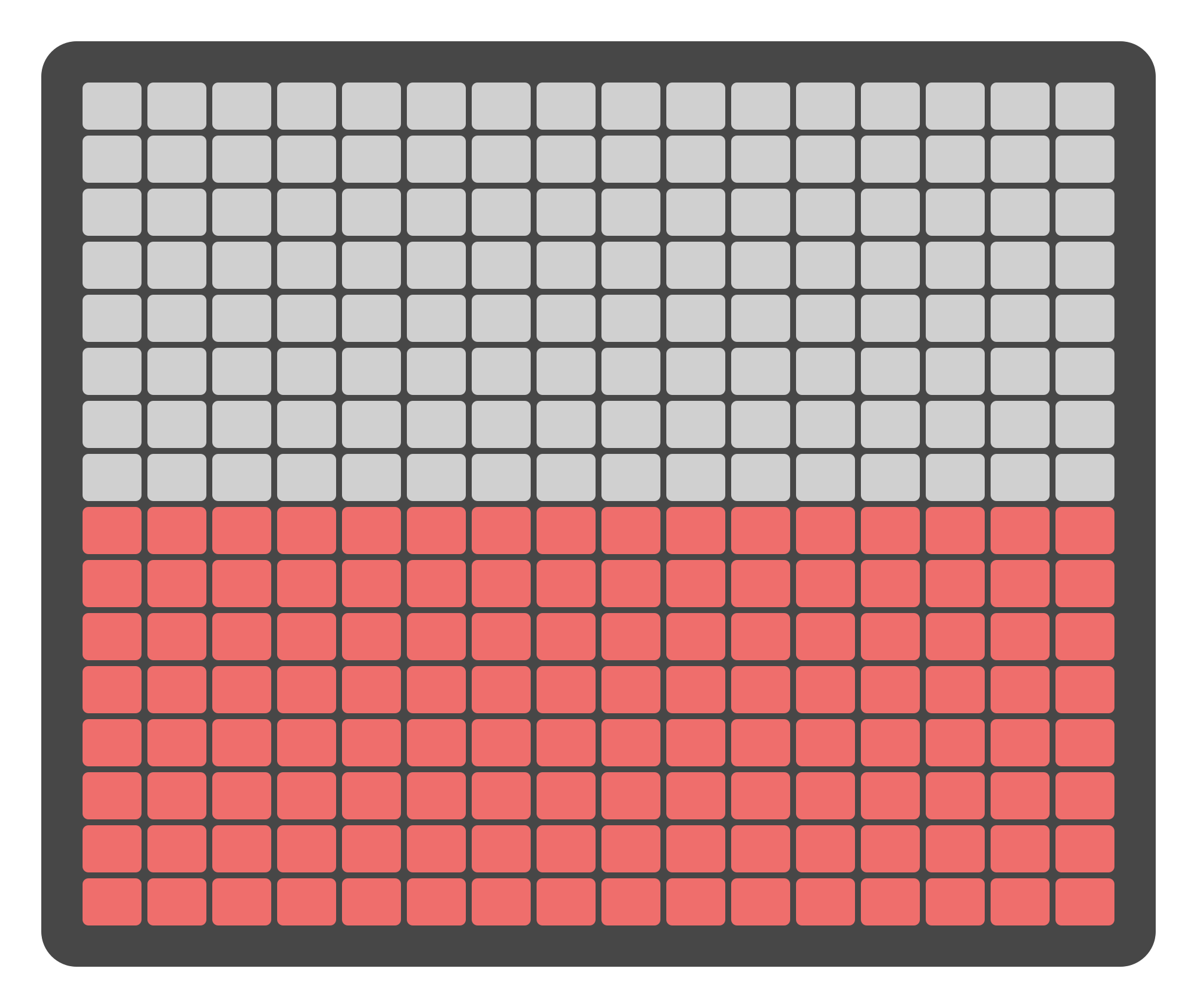
Attenuation adjustments can be made in two ways: using the Grid Pads for quick changes or using the Encoders above the display for more precise control. Clicking the Joystick Encoder upwards assigns the encoders to the inputs, while clicking it downwards assigns them to the outputs.
Attenuation Control
There are two primary methods for adjusting attenuation levels on the Mix Page:
Using the Grid Pads
The Grid Pads are divided into two sections: the top section represents virtual faders for the 16 inputs, and the bottom section represents virtual faders for the 16 outputs. Pressing a Grid Pad within each section adjusts the attenuation levels for the corresponding fader. This method allows for quick and efficient level adjustments.
Pressing SHIFT + the lowest pads in a section sets the levels to the lowest amount.
Note
Input and output levels on the Mix Page are expressed as percentages representing relative attenuation, not absolute signal volume. At 0%, signals are attenuated by approximately 63 dB on the inputs and 58 dB on the outputs. Some signal may still be faintly audible depending on the source and environment. This behavior is expected and reflects the analog nature of the mixer circuit design.
Grouped Channels
Grouped channels move proportionally when the level of any channel in the group changes. This preserves the ratio between grouped channels and allows mixing stereo or multichannel groups while keeping their original balance.
To change the balance between grouped channels without ungrouping them, long-press a channel’s pad to enter Parameter Lock, then press another pad in the same group/fader to set the relative adjustment.
Using the Encoders
The 16 physical encoders located above the screen can also control attenuation levels . Moving the Joystick Encoder upwards switches the main encoders to control the input levels, while moving it downwards switches them to control the output levels. This approach provides precise control over attenuation settings.
Select inputs levels with
Select outputs levels with
Naming Inputs, Outputs and Routings from the Mix Page
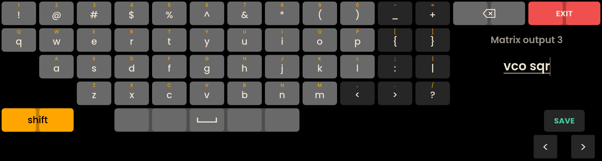
The Mix Page allows for the naming of inputs, outputs, and routings similar to the Matrix Page. By pressing the Page Button below the routing or In/Out name, the reliq keyboard will open allowing for the naming of the selected item.
For more detailed information on naming Inputs, Outputs and Routings, refer to the Matrix Chapter.
- The following buttons are used for additional keyboard functions:
Button: Toggles between lowercase, uppercase, and special characters.
Buttons: Move the cursor left or right within the name field.
Button: Saves the name and closes the keyboard.
Button: Copies the name currently being edited. NEW
Button: Replaces the name currently being edited with the copied one. The copied name is kept until you copy another, and can be pasted into any name on any page. NEW
Button + Backspace: Clears the whole name. Backspace on its own removes one character. NEW
Note
A name changed with the Reliq Keyboard can be undone. Press UNDO on the page where you made the change to restore the previous name. UNDO has no effect while the keyboard is open. NEW
Select on the Mix Page
Use Select Mode to act on several faders at once. The mechanics that are the same on every page are described in Select Mode. This section covers what is specific to the Mix Page.
With Select Mode on, press any Grid Pad in a fader’s column, or click that fader’s encoder , to add the fader to the selection. Press the pad or click the encoder again to remove it. A selected fader at 0% still lights its lowest pad, showing that it is selected.
Inputs and outputs keep separate selections. Selecting, editing, copying and pasting all apply to the bank currently shown on the display. With the inputs shown, a Grid Pad in the bottom half of the grid does not select anything, and an encoder click selects the input fader below that encoder. Move the Joystick Encoder up or down to switch bank: the grid then shows that bank’s selection.
Editing Selected Faders
Turn the encoder above a selected fader and every selected fader in the shown bank moves by the same amount as that fader.
Each fader stops on its own when it reaches 0% or 100%. Once a fader reaches an end, the differences between the selected faders are no longer kept.
If the turned fader is at 0% or 100%, turning further towards that end moves nothing. Turning back from the end moves the whole selection again.
Turning the encoder above a fader that is not selected leaves the selection alone: that encoder behaves exactly as it does with Select Mode off.
A bulk edit follows the turned fader, not the lead.
Copying and Pasting Faders
Press COPY to copy the levels of the faders selected in the shown bank, keeping the spacing they have on the grid. Hold PASTE and press a Grid Pad or click an encoder to rebuild those levels from that fader onwards. If the copied faders would run past the last fader, the display shows No space to paste here.
A paste always lands in the bank currently shown. To move a shape from the inputs to the outputs, copy the input faders, move the Joystick Encoder down to the outputs, and paste the same shape onto the output faders.
Technical Specifications
Specification | Details |
|---|---|
Attenuation (Input) | 0 to ~63dB |
Attenuation (Output) | 0 to ~58dB |